| You are not logged in. (log in or register) | |
|
|
|
How'd They Do That? :: Homage to Jacko & Rackat
Homage to Jacko & Rackat by hughletherenThe Beam Breaker User Manual
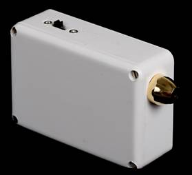
Receiver Controls and IndicatorsNote: all instructions will reference the items on the boxes from left to right and top to bottom, as shown in the photos.
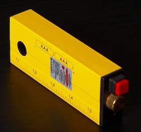
Transmitter Controls and IndicatorsThere is a simple slide switch to turn the power ON. It may require the use of a fingernail to operate; it can stick if you push it with your finger! Always check the operation by pointing the transmitter at a wall or the floor; never look directly at the laser yourself, nor point it at anyone’s face. For the alternative transmitter, a cut down laser spirit level, the switch is push for ON, push for OFF. Set UpWith SW1 OFF, check that all the connections are correct by pushing SW2 UP – the camera should auto-focus with an audible beep. Holding SW2 UP, also push SW3 UP and the shutter (and flash, if connected) should operate. Make sure both the transmitter and receiver boxes are firmly fixed to suitable solid supports, such as a table or bench, or use retort stands, either side of where you want to create the beam which will be broken. With SW1 ON, point the laser transmitter beam, with laser light ON, at the photo sensor. The laser beam makes it glow by reflected light and the green LED should light. Turn SW1 and the laser light OFF except when ready to take a photo to conserve battery power. Arrange your subjects; manually focus the camera with the falling object in the expected capture position and you should be ready to go! Make sure the camera and flash are turned on and are ready to fire. You should have the shutter set to single shot. If you have it set to multiple shot, the camera shutter will operate every time the beam is broken, which can be a nuisance. OperateTurn the laser light ON; turn SW1 to ON, SW2 to OPERATE and then SW3 to OPERATE. At this point any interruption, intended or otherwise, to the beam will cause the LED to go out for the duration of the interruption and the shutter and the connected flashes to operate. After the shutter has fired put SW3 and then SW2 into the centre OFF position. You should not be able to fire the shutter again nor will you be able to operate the camera manually until you have completed these last two steps. If you are using a laptop to capture your images, it will not record them until the two switches are OFF. This can be frustrating but is a feature of the way the remote switch works! You can take further shots by setting SW2 to OPERATE and then SW3 to OPERATE and breaking the beam. Reset SW3 and then SW2 to OFF after each shot. Understanding TimingThe shutter and flash operate at the same time but at a fixed time after the beam is broken. This time is a function of the camera, driven by its’ own internal processor and differs from model to model. This needs to be taken into account when planning your shoot. You need to calculate where the object you want to capture will be in relation to the beam when the shutter operates. I measured the camera delay by measuring the height a nut has to fall from a stationary start, breaking the beam at the start of the drop. In the photo below, the laser was aligned with the bottom of the tape at 14˝ inches. The drop I recorded for the 300D, 10D and 20D were all between 4˝ and 4ľ inches. This equates to a delay of roughly 150ms. 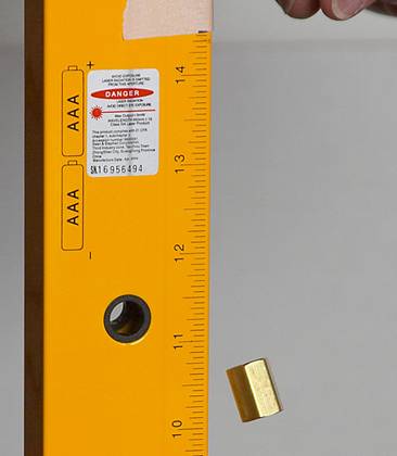 Measuring Camera Delay Some Maths
The Turkey Baster ShotSo, if you want to catch a water drop as it hits the surface of the water, you need the turkey baster about 4 ˝ inches above the surface of the water, assuming you align the beam with the bottom of the baster. Actually, in order to catch the splash, you need it a bit higher, to give the splash time to form. For the Déjŕ Vu shot, I had the turkey baster 6 inches above the water and the beam breaker 2 ľ inches above the water, the two heights achieved by trial and error. Using the maths above (after the event), I reckon it took about 100ms for the splash to form! Back to page 1
Home -
Challenges -
Community -
League -
Photos -
Cameras -
Lenses -
Learn -
Help -
Terms of Use -
Privacy -
Top ^
DPChallenge, and website content and design, Copyright © 2001-2026 Challenging Technologies, LLC. All digital photo copyrights belong to the photographers and may not be used without permission. Current Server Time: 07/22/2026 05:34:48 PM EDT. |

 Homage to Jacko & Rackat