| You are not logged in. (log in or register) | |
|
|
|
How'd They Do That? :: Homage to Jacko & Rackat
Homage to Jacko & Rackat by hughletheren
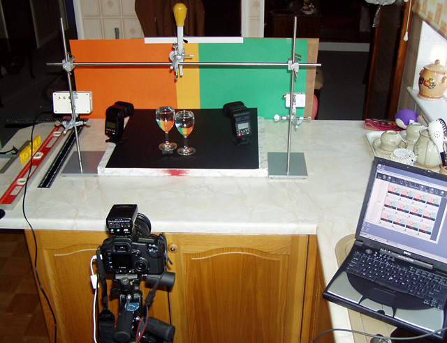
Credits: Let's not forget that Jacko was the inspiration behind this image.Ā His Primary Glass and Stripes were very striking and appealing.Ā Unfortunately Stripes didn't get a ribbon so I had to go back to the first splash I could find, Rackat's A Splash of Color to meet the spirit of the challenge.Ā Without the brilliance of these guys, there would have been no entry from me! Introduction: You can skip the words and just look at the photos and pop down to the Lessons Learned bit, if you prefer. For the hardy types, read on! It took four sessions over the Saturday and Sunday of the challenge week to achieve my goal, an image which combined the ideas behind the two images. Session 1: On the Saturday morning I set out simply (!) to repeat Primary Glass.Ā This session was a disaster.Ā I tried lighting the glasses in every way I could imagine but no matter what I did, there was glare screaming at me from the glasses.Ā Even using a brolly was awful; you could see the brolly reflected in the glass and the foot of each glass was reflected in the bowl and vice versa. Session 2a: Over a break for lunch, the penny dropped.Ā Studying the original I was trying to copy helped.Ā If you want to photograph something made of glass, especially if it is curved, light it from behind, not from the front, side or top.Ā Perhaps the best way is to bounce light off the background, allowing the glass to simply modify the image of the background. Although it took a while to get the setup right, I found I could reproduce a fair imitation of Primary Glass.Ā I used different colours to differentiate my efforts from the original.Ā I chose orange/yellow/green because they follow each other in the rainbow, orange and green contrast well and yellow is a bright, light colour suitable for reflection.Ā To those who did not like my choice, I'm sorry; to those that did, thank you! It proves once again that you can't please all the people all the time. Let's have a look at the setup
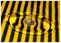
Please ignore the vertical and horizontal steel bars and their attachments - we'll explain them later. The camera, fitted with a 28-135mm zoom, IS USM lens, set at around 70mm, was tripod mounted. The glasses were sitting on a mat black card, on a piece of old kitchen top.Ā The background was three pieces of coloured card, held in place by a piece of plastic right-angle section, clamped to a piece of plywood with a G clamp, the whole thing resting on two chairs, pressed against the back edge of the worktop.Ā Two 550EX flashguns sat behind the glasses, aimed at the intersections of the coloured cards.Ā The camera was also fitted with a ST-E2 infra red flash remote controller.Ā Maybe you could do this bit with incandescent lighting but I needed the flash for later.Ā The laptop was connected to the camera and recorded the images as they were taken, using the Canon DPP package, with the remote capture facility.Ā This was not essential but it helped to be able to review a full size image as I went along.Ā The shutter could be operated either manually, using a wired remote switch or using the laptop. The most important tools were the set square, spirit levels and ruler.Ā The worktop had to be level (or the water in the glasses would not have been level), the backdrop had to be square to the glasses, the centre of the camera lens had to sit on the centre line of the glasses, with the photo sensor plane parallel to the backdrop.Ā It all sounds so obvious but it required a great deal of patience.Ā If any of these straight and square requirements weren't met, the resultant image would have been distorted or poorly focused somewhere in the image. Getting the positioning of the cards right was a pain and would have been much easier if I had had an assistant - but I didn't.Ā And it still wasn't right in the photo when it looked right in the viewfinder.Ā I had to take several shots, adjusting the position of the cards each time before it was just right. By the way, if you ever try anything like this, mark the positions of all the key items (camera, flashguns, glasses, etc.) in soft pencil, so that if anything gets knocked, you have a chance of getting it back in the right place fairly quickly.ĀĀ I learned this through bitter experience. Filling the glasses with water was a surprising challenge.Ā I had to make sure that the glasses were spotless and found that I needed to use boiled (and cooled) water to prevent bubbles forming on the sides of the glass.Ā Cold water from the fridge or the kitchen cold tap (faucet) was dreadful. At this stage, getting the camera height and up/down tilt right was less important - it was possible to shoot from slightly below the level of the rims of the glasses without it being noticeable.Ā I suspect this was the case in the original Primary Glass shot.Ā The following shot is an un-retouched version of the result at this stage (increased saturation, levels, USM, resize but no cloning, etc.)
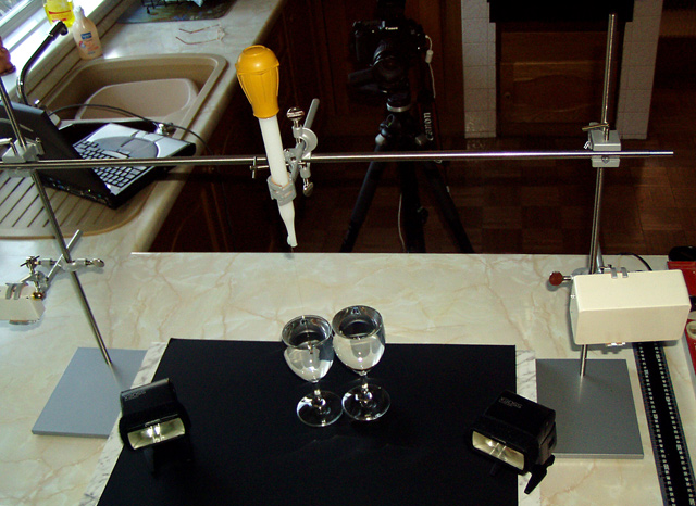
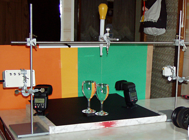
Session 2b: Then the fun started! It was time to try and catch a splash. The setup pictured above includes two retort stands with clamps fitted to them to support the two white plastic boxes, which make up my beam breaker electronics.Ā I also had a cross bar to brace the retort stands and provide a fixing for another clamp for the turkey-baster which supplied the drops of water. I used the beam breaker to fire the shutter and flash each time a falling drop of water was produced when I squeezed the turkey-baster.Ā Aligning the beam and water drop was difficult and the baster would empty its contents in a gush sometimes.Ā As a result, the rest of this session was disaster, with water overflowing onto the black card and some bad temper when I discovered that I had overwritten some almost acceptable images.Ā At least it made me try again the following day, producing better results. Session 3: The following morning, while waiting for news of the progress of our daughter-in-law's labour, I practised getting the beam breaker set up properly, to correctly to catch the water splash.Ā My wife needed her kitchen, so this was done in the hall (lobby) on the floor, without the coloured backdrop, just some white card.Ā I had used the beam breaker before with my 300D but this was the first time with the 20D on a time sensitive project.Ā I soon discovered that the shutter delay was less than with the 300D and the height of the turkey-baster and beam breaker needed some experimentation before I got it right. For those interested in the beam breaker, a more detailed description is available later.Ā It would be possible to shoot this without a beam breaker, using infinite patience and loads of shots. I note that many DPC'ers do just that.Ā However, once it the beam breaker is set up, you can take as many shots as you like, safe in the knowledge that you will catch the splash perfectly every time. For the final shot the turkey-baster was 6" above the water and the beam was set at 2.75" above the water.Ā Using a small spirit level to set the baster vertical stopped it gushing unexpectedly!Ā I also discovered a handy way of aligning the turkey-baster to the beam (or vice versa), something which had eluded me. I hung a piece of cotton thread with a small nut on the end from the side of the turkey-baste nozzle, using blu-tack.Ā The water in the glass helped to dampen the tendency of the thread to swing.Ā The beam lit up the thread when the baster was in right position (front to back).Ā It still need manual adjustment to get the position correct from left to right.Ā I also painted a small block of wood black so that I could raise the left hand glass, providing (imho) a better, more balanced composition.Ā In retrospect it might have been better if the block had been larger but not taller and part of the composition, rather than being hidden, as it was in the final submission. Then I was ready for the final session, after lunch. Session 4: The final session was fantastic.Ā I got the kitchen back and spent an hour setting everything up again but at least I knew where everything went. I spent some time getting the camera height in line with and level with the top of the right hand glass.Ā I had discovered that shooting from slightly below produced a black bubble below the water surface.Ā Then I started shooting.Ā All I needed to adjust was the shutter speed, aperture, flash compensation and the left-to-right position of the turkey-baster.Ā The moment I caught the splash, absolutely bisected was wonderful, my shout of "got it" could be heard a mile away!Ā It was only around the tenth shot of the session and I could repeat it again and again.Ā Nevertheless, it was that first one that was submitted. The bisected splash was not a fluke and achieving it was part of the original goal.Ā The submission was file 070. Here is file 076, with an alternative crop.Ā I decided this one was too far away from the original to submit but maybe it proves my point about it not being a fluke!
Post
Processing Convert from RAW at 16 bits using PS CS plug-in: 5500, -6, 0, 25, 104, +25, +25.Ā Then crop, rotate, levels,Ā increase saturation again, USM, remove glint from left side of LH glass, some (but not all) spots in glass, some (but not all) spots on the ?floor? and background, all by cloning, select ?floor? rectangle, copy, new layer from copy, add layer mask reveal all, paint out glasses from mask using soft brush, blur, clone, heal, burn to merge wooden block under LH glass with floor in top layer, combine layers with multiply (at less than 100%) to darken, flatten, mode to 8 bits, canvas size twice to create border, resize, 640 to maximum dimension, USM, save for web at 148K.
Could Do Better! I still don't like the "floor" much.Ā If I had to take the same image again, I might try a white "floor", allowing it to reflect the three background colours, although they would be in a lighter shade.Ā Maybe I would also use a white block to raise the left glass, making it part of the composition.Ā Last but not least, if the camera was moved back and the lens zoomed further in, using the foreshortening effect of the longer lens, the amount of floor visible could be reduced to be nearer that in the original.Ā Was it necessary to shoot at 1/500s?.Ā I'm not sure. Maybe a slower speed would still have frozen the action. Since I wrote this tutorial I have learned a bit about freezing movement with flash. I used ETTL throughout the production of this competition entry and varied the shutter speed to try and freeze movement. I now know that it is much better to use a fixed shutter speed, 1/250s for the EOS 50D and use a manual power setting on the flash to achieve the required exposure level. Assuming the power setting is 1/8 or less, the flash duration will be less than 1/9000s! There is an explanation of this technique here.
EXIF
Data
Lessons Learned
Time spent making sure everything is straight, square and level is time well spent.
Mark the positions of
all the key items (camera, flashguns, glasses, etc.) in soft pencil, so that if anything gets knocked, you have a chance of getting it back in the right place fairly quickly.
When photographing glassware, try lighting it from behind, preferably using bounced light from the background, to avoid distracting glints.
Clean the glasses before setting them up and check them for flaws.Ā Fill them with previously boiled water if bubbles are a nuisance.
Check the exposure histogram for each channel (RGB); do not rely on the luminance histogram on the camera, it will only tell you about blown white highlights, not individual channel clipping.
A beam breaker can take much of the chance factor out of the equation but it takes time and care
to set up.
Make sure your source of water drops is vertical, using a spirit level, to stop it gushing unexpectedly.
A blu-tacked weighted piece of thread can help with tricky alignment.
Take time to review other people's work, there is usually much more in it than you realise at
first.
It is always worth trying moving the position of the camera towards and away from the subject, rather than relying on the zoom because it has a different effect, especially on perspective.
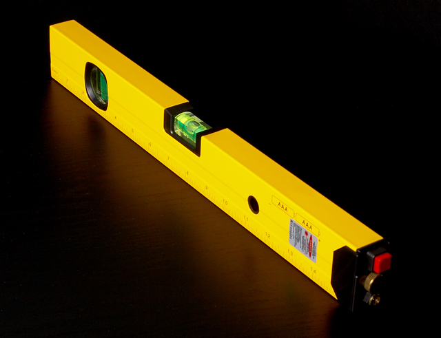
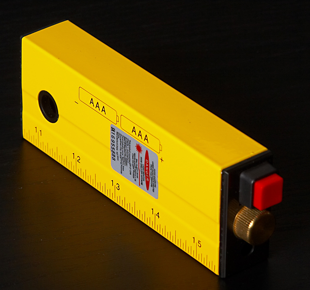
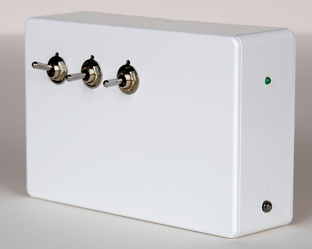
The beam breaker has a transmitter, the small white box in the clamp on the right.Ā It is just one of those cheap laser pointers you can buy in a garage (filling station), repackaged in a small box with a switch and three AAA cells replacing the mercury button cells.Ā You could use a laser pointer "as is" but the switch has to be held in the "on" position and the mercury cells do not last very long. The beam breaker has a receiver, the larger white box in the clamp on the left.Ā Maybe one day I will describe how to make one (or maybe even go into production and sell them!) but not now.Ā You can buy beam breakers on the internet which are much more sophisticated than mine, with a programmable delay and sound activation and such-like but they are expensive.Ā Mine is very simple and cheap.Ā It is battery powered. The laser pointer shines on a phototransistor which lights an indicator LED and holds off the fire-the-shutter-line which is connected to the camera remote socket .Ā When the light beam is interrupted, say by a drop of water falling through the beam, the warning LED goes out and the fire-the-shutter line activates. The flash fires in time with the shutter, driven by the ST-E2 remote controller.Ā There is a delay in the camera between the fire-the-shutter activation and the shutter operating.Ā This varies from camera type to camera type but for the EOS 300D, 10D and 20D it is around 150ms.Ā Fortunately this delay means that we can arrange the drop to break the beam on its way down, firing the shutter and flash at the moment the splash is created. For the 300D, the beam breaker mounted just below the end of the turkey-baster, 4" above the water level would catch the drop just as it hit the water, before the splash was formed.Ā For this exercise, with my 20D, the turkey-baster was 6" above the water, with beam breaker 2.75" above the water, giving time (around 100ms) for the splash column to form. There is some schoolchild maths behind all this, which I used to calculate the times given above.Ā The water drop accelerates at 32 feet per second per second under the influence of gravity.Ā With a water drop falling 6", it is travelling at 5.65 feet per second when it hits the water!Ā You can find the maths in the user manual. ĀEnough people have asked "How do I Build a Beam Breaker?" for me to write it up - so here goes!Ā If you don't want to build your own beam breaker, you have reached the end of the tutorial!
Disclaimers Please make sure you read the laser warnings on your laser device, they can be harmful.Ā Never point the laser at anyone and never look directly at the laser beam, it can permanently damage your sight. Introduction However, the method of connecting the IC was a bit unconventional, as you will see if you look at the photos.Ā I recently tried and succeeded in building a design without the IC, which it will be easier to build and that is what I will describe.Ā There is a schematic of the more complex version here, so you can have a go if you wish.Ā The simpler version doesn't snap so clearly between light and dark and requires a little more care in avoiding stray light on the sensor but it does work satisfactorily. The circuit diagram for this version can be found here. Do you have the necessary skills to build a beam breaker yourself?Ā The electronics is trivial and an understanding isn't necessary but you do need to be able to use a small soldering iron and you do need both tools and the manual
dexterity to do the mechanics. Cost The Tools The Transmitter 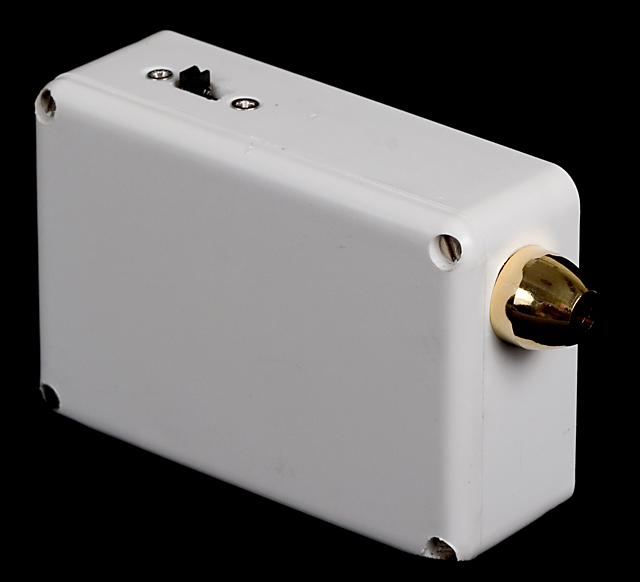
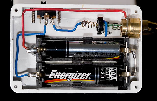
It was relatively cheap, less than $20 and came apart with the application of a little patience and a modicum of brute force.Ā You need a laser which you can switch on and switch off and pointers tend to have a spring loaded press-and-hold switch which is not practical; hence the need to take it apart.Ā I then built it into small white plastic box (25mm x 50mm x 75mm or 1" x 2" x 3"), incorporating a slide on/off switch and two AAA battery holders.Ā AAA cells last much longer than the mercury cells that came with the pointer - you need one AAA cell for each mercury cell.Ā Some pointers have two, some have three.Ā You may be able to work out how to build it yourself, using the photos as a guide.Ā (Note:Ā The positive connection goes to the case and the negative connection goes via the switch to the spring connection.Ā I tied a piece of blue wire around the little board to hold the inbuilt switch permanently on.)Ā However, you do not need to build your own transmitter as you can now buy a ready made solution. During my recent visit to the USA, I discovered that most hardware stores now stock spirit levels with a built-in laser which has a push-for-on, push-for-off switch. This is an ideal solution and does not require any modification at all. I bought a couple at Harbor Freight for $7.99 each!Ā While you may have to pay a bit more outside the USA, try your local hardware store or visit this Harbor Freight link: DOT & LINE LASER LEVEL
I couldn't resist cutting one down, as you can see.Ā The black end cap without the laser in it pulls out.Ā Do not try and pull the laser end out, you will break it.Ā It is glued in place, as is one of the connecting wires and the inside of the unit is not suitable for this application.Ā How do I know?Ā How do you think?Ā I did manage to repair it and put it back together in the cut down case but this really isn't necessary.Ā By the way, for the beam breaker application, you take off the lens holder, seen in bottom rightĀ hand corner of the first photo, projecting back from the end cap, but not in the second (that was lucky, I didn't plan the photos that way!).Ā The lens produces a line and you need a spot. The Remote Control
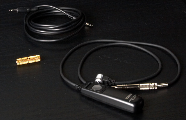
Switch If you have any other EOS camera, it will probably have an N3 connector for the remote switch. The only way I know of procuring that connector is to buy the Canon RS-80N3 remote switch.Ā It cost around $50 to $60 (around the same in Ż) although there are after-market versions around on the web at about $20. Having bought this expensive switch, complete with its lead and connector, you will have to butcher it!Ā OMG!Ā This will invalidate any warranty on the remote switch too!Ā Cut the lead in half and fit a 3.5mm stereo jack to the switch half and a 3.5mm stereo socket to the connector half. Connect the red wire to the centre or tip pin (right channel), the white wire to the middle (left channel) and the screen (the outer layer of bare wires) to the outside case. You may need a continuity checker to make sure you get it right.Ā Put the jack in the socket and check that the remote switch still works as it should when connected to the camera.Ā It should provide the same functions as the shutter button on the camera - half press causesĀ the auto focus and exposure to work (and the viewfinder screen shows the settings) and a full press fires the shutter.Ā You will use a ready made 3.5mm stereo jack to jack lead to connect the camera to the beam breaker receiver.Ā If you ever want to use the remote switch on its own and it isn't long enough, you can buy a ready made 3.5mm stereo jack-to-jack and a back-to-back socket or buy a jack-to-socket lead - I have found both at Radio Shack.Ā So it was worth butchering the remote switch after all!Ā The photo (black on black, hmm. . . ) shows my kit.
The Receiver Components How to Build The Receiver Part 1 - The
Mechanics
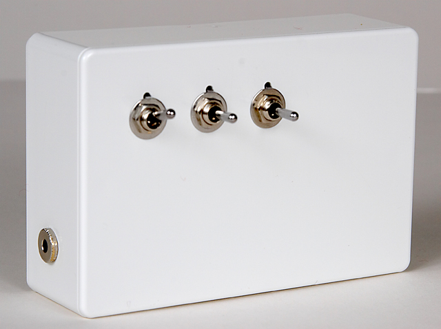
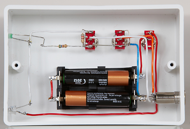
The photo below is used throughout to provide orientation and shows the inside of the receiver from the back, the lid forming the back panel and the bottom of the box is used as the front face, with the switches mounted in it.
Using a pencil and the set square, measure and mark a vertical line down the middle (measured with the lid on) of the outside of both the left and right hand sides of the box. Mark a horizontal line 20mm or 3/4" from the bottom on the right hand face (as seen from the back). Make a dimple in the surface at the intersection of the two lines with a centre punch or a sharp point.Ā This marks the hole for the stereo jack socket.Ā Mark a horizontal line 20mm or 3/4" from the top on the leftĀ hand face (as seen from the back). Make a dimple in the surface at the intersection of the two lines with a centre punch or a sharp point.Ā This marks the hole for the green LED. Repeat the procedure for the photo transistor hole, measuring from the bottom of the box.Ā In my latest version, instead of 20mm from the bottom of the box, I measured the vertical position by putting both the receiver box and the spirit level laser on a flat surface and marking the point where the laser spot appeared on the receiver box, which was about 10 mm up.Ā This means that the two holes on this face are not symmetrical but if the two boxes are used on separate surfaces at the same height, you don't have to fiddle about getting the height of the laser spot right. Please suit yourself! Turn the box round and mark a horizontal line on the front face 20 mm from the top, about 70mm long, measured from the left as you look at the front.Ā Mark three vertical lines 20mm apart, the first 20mm from the left hand edge. Dimple the intersections.Ā These mark the holes for the three switches. You now have the positions marked for the six required holes.Ā Using a 1mm drill bit, drill pilot holes at each dimple.Ā Increase the size of each relevant hole with larger drill bits in small steps until you have a push fit for the photo transistor (about 5mm) and the LED (about 3mm).Ā Use a slow drilling speed, plastic gets hot and melts if you go fast.Ā A hand brace works fine as long as you clamp the box.Ā Open up the three switch holes gradually, checking the fit of the switches.Ā Mine ended up at 6mm.Ā If your switches come with a location washer, you can fit it or not as you wish. I did and the locating holes were about 1.5mm in diameter, 15 mm from the top edge or 5mm up from the centre of the switch holes.Ā If you are going to use the locating washers, mark their positions at the same time as the other holes. Fitting the jack socket is a challenge.Ā The chassis mounting type is designed for a thin metal box and the plastic box is a bit too thick for the threaded portion.Ā On my first two models I used a countersink bit, gingerly and gently, until I could just get the threaded round nut to fit.Ā On my latest model I used a cable end type of jack socket which has a longer threaded portion and requires a much bigger hole.Ā I had originally intended to cut the case of the socket to make a round nut but found that by getting the hole size right, I could create a thread in the wall of the box by screwing the jack socket into the hole.Ā It took some patience but it produced a better looking finish.Ā Fit the socket with the two terminal facing up at you with the screen connector underneath. Fit the LED and photo transistor, which should both be a push fit but only so that the tops just protrude, not all the way.Ā The flat on the side of the photo transistor should face the bottom, as should the longer leg on the LED. Neither will come to any harm if connected the wrong way round, although the beam breaker won't work!Ā Then fit the jack socket and switches firmly in the box. Fix the battery holders top to toe, + on the top one to the right, + on the bottom on the left, to the bottom of the box, as shown in the photo, using double sided foam sticky tape.Ā If you can, align the bottom holder so that the negative connector tab sits just above the case connection on the jack socket, which will save one wire. Part Two - Wiring
It Up Solder the negative (-)(i.e., right) side of the bottom battery connector to the case of the jack socket. Solder a red wire between the two left hand terminals of the battery boxes. Solder a red wire from the top right battery connector to the centre connector on the right hand switch. Solder a bare tinned copper wire from the bottom connector of the left hand switch to the bottom connector of the middle switch and then to the top connector on the middle switch.Ā If you are using all two-position instead of three-position switches, PM me for the alternative instructions. Solder a blue wire between the jack socket case (battery negative connector) to the bare tinned copper wire you have just installed. Solder a white wire between the middle connector on the left switch to the connector nearest the bottom of the box on the jack socket. Solder an orange wire from the middle connector on the middle switch to the jack socket connector
which faces the top of the box. Solder a white wire between the adjacent wires on the LED (bottom) and photo transistor
(top). Solder a white wire between the lower lead on the LED and the top connector on the left hand switch. Solder an 820 ohm resistor between the top and bottom terminals of the left hand switch. Solder a 560 ohm resistor between the bottom connector of the left switch to the upper wire on the LED. Connect a red wire between the lower photo transistor lead and the top connector on the right hand switch. Insert two AAA batteries in their holders.Ā Put all three switches down (ON). Nothing should happen!Ā Now shine the laser at the photo transistor and the green LED should come on.Ā If it does, you are a hero/heroine! If it doesn't, check and double check that you have followed all the instructions.Ā If you haven't, put it right.Ā If you have, PM me and we will try and find out what is wrong with these instructions!!! Part 3
- Testing Then with the right two switches at centre, turn the left switch to ON (down). Then push the middle switch down (ON) and the camera should autofocus. Then push the right switch down and the shutter and flash should fire.
Now turn middle and right switches to centre.Ā Align the laser on the photo transistor, the green LED should come on.Ā Without disturbing the laser from shining on the photo transistor, turn the middle switch to down and the camera should auto focus.Ā Push the right hand switch down and nothing should happen until you break the beam, when shutter and flash should fire.Ā Wow! Go and read The Beam Breaker Draft User Manual Āand try it out! What Can Go Wrong If the LED does not light when it should, it may be that the LED is wired back to front.Ā Try reversing the connections.Ā If it still does light, try reversing the connections on the photo transistor.Ā The flat on the photo transistor case identifies the side that should go through the switch to battery positive. If the LED stays on all the time, you may have too much light falling on the photo transistor.Ā Try shielding it from any bright light other than the laser. Still stuck - PM me! Please PM me if you succeed - it would be nice to know that the effort was worth it.Ā My thanks to the several members who have told me of their successful build of the beam breaker. Four years on and I am still playing with the beam breaker. I have just added a delay facility which makes the setting up process a bit easier and allows me to increment the delay between shots so that you can produce a series of time sequenced shots, like The Anatomy of a Water Drop. You can find the circuit diagram here. I'm afraid it is a bit too complicated to write up a set of wiring instructions but the electronics enthusiast might wish to have a go!
Home -
Challenges -
Community -
League -
Photos -
Cameras -
Lenses -
Learn -
Help -
Terms of Use -
Privacy -
Top ^
DPChallenge, and website content and design, Copyright © 2001-2026 Challenging Technologies, LLC. All digital photo copyrights belong to the photographers and may not be used without permission. Current Server Time: 08/01/2026 09:35:10 PM EDT. |

 Homage to Jacko & Rackat